Dec 30, 2021
5G – Understanding Network and Security for Far-Edge Computing

As of August 2021, 175 MNOs were operating public 5G services across 72 countries[9]. It is estimated that 5G networks will account for 77% of MNO revenues (600 billion USD) by 2026, with demand for both consumer and business services such as MEC driving adoption. Much of this is being driven by the massive deployment of cellular-connected IoT devices, which are predicted to top six billion by 2026. That will be the point where IoT devices overtake smartphones as endpoints on mobile networks, with half of these expected to use 5G connections.

5G benefits from widespread support as a single global standard. When the specification was developed, the primary design goals were as follows:

Peak data rates up to 10 Gbps

Reliable, deterministic low latency for critical applications

Much higher density of devices on the network

Network Functions Virtualization (NFV) capabilities built into the core

Ability to fine-tune Quality of Service (QoS) parameters per application

At the same time, they realized that MNOs had made considerable investments in 4G/LTE infrastructure. Therefore, the specification was formulated in such a way that brand-new end-to-end 5G networks were not a requirement. Deployments are typically done in a phased manner that allows elements of an MNO’s network to be upgraded over time:

Figure 3.23 – Example of a 5G network

Even where standalone/private 5G networks are built using the full 5G New Radio (5G NR) architecture end-to-end, User Equipment (UE) such as mobile devices themselves are often built in a hybrid way such that 4G/LTE acts as a fallback position in case of incompatibilities.

5G Core (5GC) architecture

5G Core (5GC) is the basis of the network architecture used in 5G (fifth-generation) mobile networks. It is responsible for providing the same core network services as EPC, but it has been redesigned to support the increased demands and requirements of 5G networks. Compared to 4G/LTE EPC, 5GC was designed to be more flexible and scalable, with the ability to support a wider range of use cases and network architectures.

5GC includes the following key elements:

Access and mobility management function (AMF): Manages authentication, radio resource management, handover management, connectivity to external networks, and management of QoS for user data plane traffic.

Session management function (SMF): Manages the establishment, maintenance, and termination of sessions between the mobile device and the network.

User plane function (UPF): Routes user data plane traffic between the mobile device and the network. It is also responsible for compressing packets and enforcing the QoS policies set by the AMF:

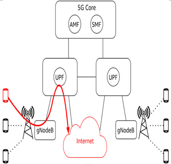
Figure 3.24 – 5GC logical architecture

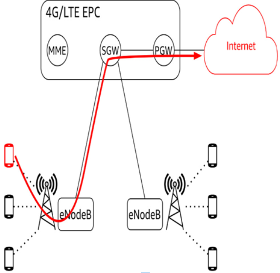
In the preceding figure, we can see that, unlike the PGW in 4G/LTE EPC, there is no longer a single node acting as the gateway to the internet or other packet networks. Mobile devices no longer need to backhaul to the PGW to leave the cell provider’s network. Elimination of this bottleneck was needed to support the much higher density of mobile devices, which is a key use case for 5G:

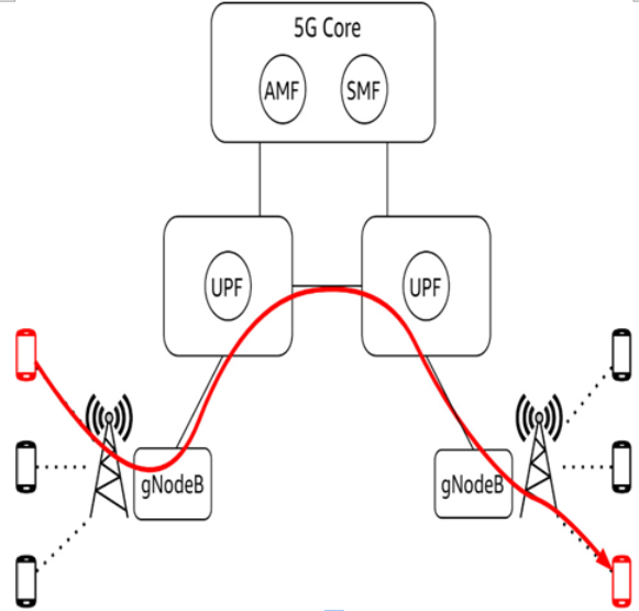
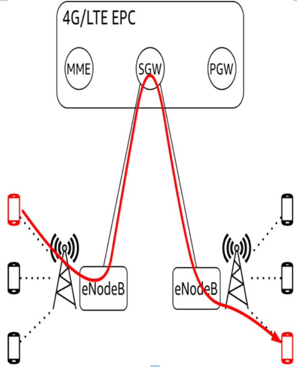
Figure 3.25 – 5G intranetwork routing

The preceding figure illustrates how the data path between two mobile devices on the same network benefits from 5GC’s distributed UPF. These changes are a key reason 5G devices see average RTTs of <10ms versus the average of 50ms observed in 4G/LTE networks.

More Details
Oct 15, 2021
Utilizing cellular networks – Understanding Network and Security for Far-Edge Computing

In this main section we will take a closer look at the different cellular networks and understand how we can utilize them. We will mainly cover 4G/LTE, 5G, C-V2X, and NB-IoT.

4G/LTE

What is known as 4G/LTE is not a single specification. It is a family of technologies that set out to meet a proposed definition of 4G laid out by the ITU in 2008. Its designers had the following improvements in mind over 3G:

Fully packet-switched (3G was circuit-switched)

Peak data rates up to 100 Mbps for mobile devices

1 Gbps for stationary devices such as 4G hotspots

Increased density of devices per cell through resource sharing:

Figure 3.20 – An example of a 4G/LTE network

How 4G/LTE is implemented varies considerably between Mobile Network Operators (MNOs). There are also key differences in how a given MNO’s 4G/LTE network functions across regions9. MNOs began rolling out 4G/LTE networks around 2011, and it was 2016 before MNO coverage could be considered widespread.

9 The Americas, Europe, Africa, and Asia all had different regulatory constraints that drove this.

Evolved Node B (eNodeB)

The part of a 4G/LTE network you are likely most familiar with is the front end – the ubiquitous cell tower. In 4G/LTE parlance, these are known as eNodeBs. They are elements of a standard cellular network component known as the Radio Access Network (RAN). They include antennas, transceivers, and radio access controllers.

Evolved Packet Core (EPC)

Note that 4G/LTE base stations (eNodeBs) only communicate with each other directly for control plane functions, such as to hand off a device from one tower to another.

Figure 3.21 – 4G/LTE logical architecture

Otherwise, communication needs to go through one of the subcomponents of EPC:

Serving gateway (SGW): Routes user data plane traffic, either between mobile devices or out to other EPC functions, such as a Packet Data Network Gateway (PGW). It also provides core network services such as routing, switching, and transport of data packets.

Packet data network gateway (PGW): Routes user data-plane traffic between EPC and external IP networks such as the internet. It’s also responsible for handling the exchange of data between the mobile device and the wider internet, and it consists of several interconnected network elements.

Mobility management entity (MME): This handles critical control plane functions for mobile devices, including authentication, location tracking, and handover signaling.

4G/LTE latency

EPC instances are centralized and often physically distant from the eNodeBs in a cellular network.

Figure 3.22 – 4G/LTE hairpin routing

Because user data plane traffic has to go back up to the EPC layer to be routed (this is known as hairpin routing), the average RTT on 4G hovers around 50 ms.

More Details
Aug 18, 2021
ORTHOGONAL FREQUENCY DIVISION MULTIPLEXING (OFDM) – Understanding Network and Security for Far-Edge Computing

This is a scheme in which multiple closely spaced orthogonal subcarrier signals with overlapping spectra are transmitted to carry data in parallel.

In traditional Frequency Division Multiplexing (FDM), the subcarriers (also known as channels) are kept apart using a little bit of space between them called a guard band:

Figure 3.18 – FDM using guard bands

This is done to prevent crosstalk, noise, or interference between the channels. It also makes it easier for the demodulators to single out the channels when demuxing them.

OFDM deliberately overlaps the channels in a specific way – this is where the orthogonal part comes in. Orthogonal means “at right angles,” but in this context, it refers to a precise mathematical relationship between how the channels are spaced across the frequency band. This technique can save as much as 50% of the bandwidth, which can now be used to carry additional channels:

Figure 3.19 – OFDM

OFDM uses digital signal processing techniques to perform coherent demodulation on these overlapping channels 7. The mathematics are beyond the scope of this book. At its core, this is simply another example of how we can exploit the fact that light always travels at the same speed. OFDM techniques can, and often are, used in combination with MIMO.

7 Fourier transforms can be performed to convert the time domain of a digital signal’s square waves into frequency domains corresponding to the channels.

Shannon-Hartley theorem (signal-to-noise ratio)

Developed in the 1940s, the Shannon-Hartley theorem describes the maximum rate at which information can be transmitted over a communications channel of a specified bandwidth in the presence of noise:

Here, we have the following:

C is the channel capacity in bits per second

B is the bandwidth of the channel in hertz

S is the average received signal power in watts

N is the average power of noise/interference in watts

Let’s zero in on the two most important terms to remember:

Signal (S): Average power of the received signal in watts

Noise (N): Average power of noise (that is, interference) in watts

These two terms are grouped into a single expression known as the Signal-to-Noise Ratio (SNR). An SNR of 2:1 means there is twice as much signal as there is noise. An SNR of 1:1 means there is the same amount of noise as there is a signal.

Another way to put this is to say a signal that is suffering throughput loss from degradation due to interference can be improved by increasing the signal’s power 8.

8 Keep in mind that increasing the power of your signal can create interference for others. This is why there are often laws limiting how powerful a given device’s transmitter is allowed to be.

More Details